Hi Ivan, the RST column in the Manual shows the values of the field at reset, and an ‘x’ means undefined or unassigned at reset time. It is nothing to worry about, especially if you always explicitly initialize fields yourself.
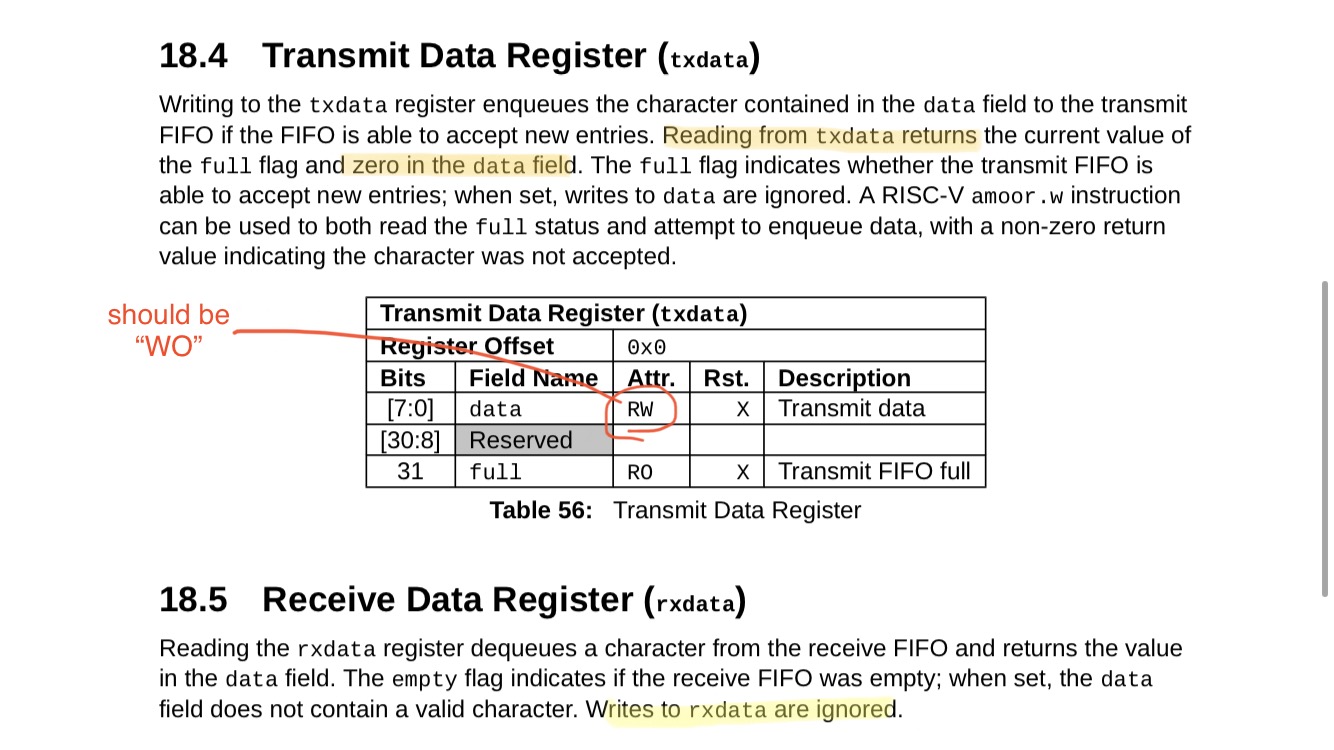
You are doing nothing wrong here. The TXDATA is a ‘write only’ register (except for the msb), so its readback value will always appear to be 0x0. Similarly, the RXDATA is a ‘read only’ register, so writing values to it have no effect.
One question: have you selected the hardware pins to point to the uart circuit rather than gpio logic? You can do this as follows. The first line selects uart/spi/i2c functions (rather than pwm) and the second line enables the hardware uart/spi/i2c/pwm circuits (rather than gpio):
GPIO_IOF_SEL &= ~((1 << 16) | (1 << 17)); // uart0 rx & tx
GPIO_IOF_EN |= ((1 << 16) | (1 << 17)); // uart0 rx & tx
gpio 16 and 17 are uart0 rx and tx (on physical pins 38 and 39), while gpio 23 and 18 are gpio1 rx and tx (on physical pins 45 and 40).
Another question: did you set up the baud rate divider? You might want to define one more register. I suggest prefixing all of your #defines with uart0_ so that you could support uart1 later.
#define uart0_sckdiv (*((volatile uint32_t *) 0x10013000 + 0x18))
Following a Helpful r-m-w style by @Seif , you could create functions to handle the fields of a register rather than the registers themselves; in other words, you decouple field from register so that higher level code becomes somewhat agnostic to asic definition.
uart0_sckdiv = ((uart0_div & ~(0xffff << 0)) | ((x & 0xffff) << 0)); // div
where ‘x’ here is decimal 138 meaning (16000000/115200)-1 or 115.2kbaud for a 16mhz core clock.
Thus, some useful #define field_name( x ) ( ... (x) ... ) hyper-macro functions might be
uart0_sckdiv = ((uart0_div & ~(0xffff << 0)) | ((x & 0xffff) << 0)); // div
uart0_txctrl = ((uart0_txctrl & ~(1 << 0)) | ((x & 1) << 0)) // txen
uart0_txctrl = ((uart0_txctrl & ~(1 << 1)) | ((x & 1) << 1)) // nstop
uart0_rxctrl = ((uart0_rxctrl & ~(1 << 0)) | ((x & 1) << 0)) // rxen
((uart0_txdata >> 31) & 0x1) // txfull
((uart0_rxdata >> 31) & 0x1) // rxempty
and obvious duplicates for the uart1_… device. The general pattern of these is below.
Your higher level reading and writing functions might look like
void uart0_write (uint8_t x) { while (uart0_txfull); uart0_txdata = x; }
uint8_t uart0_read (void) { while (uart0_rxempty); return uart0_rxdata; }
The uart actually is an eight byte fifo, so for best results you could actually write up to eight bytes without checking for _full, and watch the interrupt pending bit for completion of send, more on that later.
Oh, and to be clear, TX here means output from the FE310, going to RX at the other end. Similarly, RX here means input of the FE310, coming from TX at the other end.
General pattern of field accessors:
#define foo_bar (*((volatile uint32_t *) BASEADDR + OFFSET))
#define foo_baz(x) ( (foo_bar) = (( (foo_bar) & ~(A << B)) | (( (x) & A) << B)) )
#define foo_baz ( (( (foo_bar) >> B) & A) )
A - field width as (2^#bits) - 1, such as 0x1, 0x3, 0x7, 0xf, …
B - field position as location of its lsb (0-31), bitwise right justified
foo - name of circuit block, as in uart0, spi1, …
bar - name of register of circuit block, as in sckdiv, ie, ip, …
baz - name of field of register, as in data, txwm, full, empty, … (see caveat below)
Examples:
to set field txwm of register ie of block uart0 to 3:
uart0_ie_txwm( 3 );
To query field empty of block uart0:
uint8_t x = uart0_rx_empty;
Caveat: There is an unfortunate choice of names in the Manual, for example, both the register ‘div’ and field name ‘div’ are the same; and txwm are the same in registers ‘ie’ and ‘ip’. I suggest that field names be different (and more specific) than register names; and field names be unique across all registers of a given hardware block. Examples: for hardware block uart0:
sckdiv instead of div for register div
ie_txwm instead of txwm for register ie
tx_data instead of data for register txdata
rx_empty instead of empty for register rxdata
and so on.