SPI1 doesn't seem to work when CPU clock is under 320MHz

Hello!

I’ve had good success using the SPI and CPU configuration code provided by Kjarvel (repository here); however, I noticed that in order for his SPI code to work, the CPU must be initialized to 320MHz. At other frequencies (e.g. 16MHz, 64MHz, 160MHz), it appears that the handshake pin is never set high when it comes time to read it, and the code stalls while waiting for it.

The reason I ask is since I’d like to keep the clock running a little less intensely (e.g. around 64MHz or lower) if I can, as the CPU runs pretty hot at 320MHz. I’ve gone into the cpu.c file and modified the PLL configuration to bring the clock frequency to 64MHz, and made sure all references to the frequency in uart.c and spi.c were matched. Here’s the code I’m using to bring the frequency to 64MHz:

void cpu_clock_init(void)
{
    uint32_t cfg_temp = 0;

    /* There is a 16 MHz crystal oscillator HFXOSC on the board */
    cfg_temp |= BITS(PLLREFSEL_I, 1);     	// Drive PLL from 16 MHz HFXOSC.

    cfg_temp |= BITS(PLLR_I, 1U);     		// Divide ratio.
    										// R="1U" is treated as a divide ratio of 2.
    										// This gives 16MHz / 2 = 8MHz.
    										// This is within range for refr.

    cfg_temp |= BITS(PLLF_I, 31U);  		// Multiply ratio.
    										// F="31U" gives a multiply ratio of 2 * ("31U" + 1) = 64.
    										// This gives 8MHz * 64 = 512MHz.
    										// This is within range for vco.

    cfg_temp |= BITS(PLLQ_I, 3U);     		// Divide again.
    										// Q="3U" gives a division ratio of 8.
    										// This gives 512MHz / 8 = 64MHz.
    										// This is within range for pllout.
    PLLCFG = cfg_temp;

    delay(1000);

    while ( PLLCFG & BITS(PLLLOCK_I, 1) == 0) {} 	// Wait until PLL locks
    PLLCFG |= BITS(PLLSEL_I, 1);          			// Let PLL drive hfclk
}

I confirmed that I was getting 64MHz with a quick GPIO test. UART appears to work as intended with the CPU frequency at 64MHz, since output is legible. I also scoped GPIO pin 5 and confirmed that the SPI_SCK signal was running at 80kHz as defined (and I was able to tweak this to 40kHz and 60kHz successfully as well, not that I care to change it unless it’s necessary).

However, in no configuration at lower speeds has the handshake pin cooperated as expected. As far as I can tell on the scope, the handshake pin is never up in time for a transaction, and only sometimes appears to come up for a few microseconds, but always goes low before the pin is checked.

Here’s a healthy SPI transaction (at 320MHz with 80kHz SCK – ignore the 50kHz on screen, it’s 80 when zoomed in), where the handshake pin is up until the command is sent over and only then goes low briefly before coming back up:

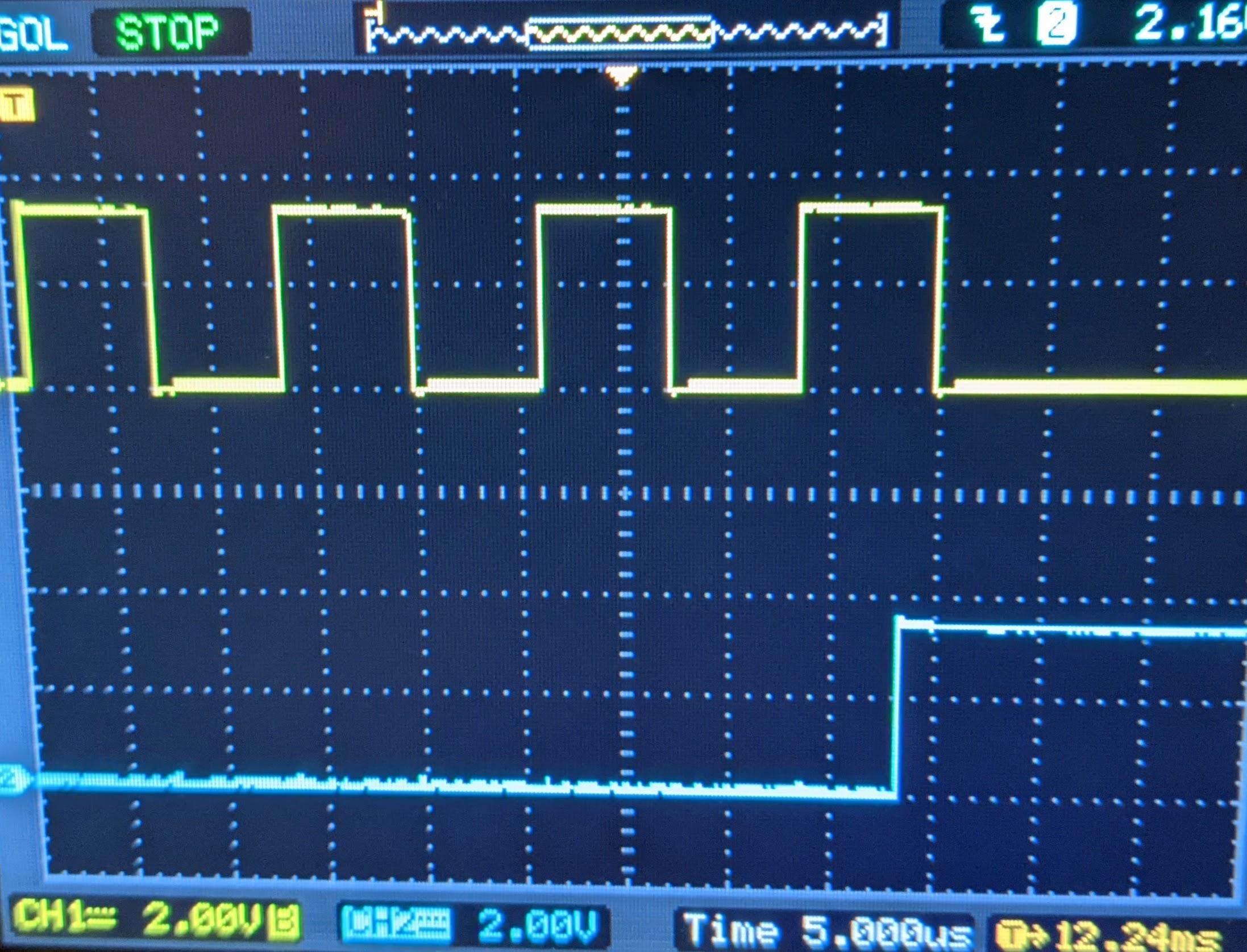
At 64MHz and 80kHz SCK, it looks like the handshake pin stays low until midway through the transaction, comes up briefly, and then goes low before the end of the transaction:

I’ve tried searching for the reason behind this, but I haven’t found any reasoning as to why the behavior of the handshake pin would change due to a change in CPU frequency. Interestingly, I’ve noticed that all implementations of SPI that I’ve found set the CPU frequency to 320MHz – I can’t tell if this is due to requirement or personal preference on the parts of the developers. Does anyone happen to know if there’s some piece of documentation around CPU frequency and the ability to properly communicate over SPI?

Thank you!

Check CS signal, it shouldn’t go high during the transaction, but it can, in theory, if you don’t feed bytes fast enough.

1 Like

Thanks for the quick reply! You were right – the CS pin was going high midway through transactions at lower CPU frequencies.

Here’s an unhealthy transaction with the SPI1_SCK in yellow and the CS pin in blue:

So, I figured I might try removing hardware control of the CS pin, and try controlling it manually.

I used this code to make the CS pin manually controlled (I also had to make sure the CS pin wasn’t included in the IOF_SPI_ENABLE macro above spi_init):

void spi_init(uint32_t spi_clock)
{
    /* Disable hardware support for CS2, and make it GPIO */
    IOF_EN &= ~BIT_MASK(SPI1_CS2);		// Disable HW control of CS pin
    INPUT_EN &= ~BIT_MASK(SPI1_CS2);   	// Take CS pin off of input
    OUTPUT_VAL |= BIT_MASK(SPI1_CS2);	// Set CS pin high by default
    OUTPUT_EN |= BIT_MASK(SPI1_CS2);   	// Set CS pin to output
    ...

Then, I made sure to set the pin low before sending each header to the ESP32, and then set it high when I was done writing bytes to txdata. I got this working, and we can see that the CS pin appears to function as intended at 320MHz:

However, I started running into a new problem: the CS pin would go high before the SPI clock was done oscillating:

I assume that this is due to a lack of synchronization between the IOF implementation and the code I’m writing, but I could be very wrong. To solve this, I looked at various methods of keeping the CS pin low until the data was done transmitting.

Attempted Fixes:

I tried using the delay0 register, but I believe that only takes effect if the CS pin is under hardware control. While modifying this register only sometimes fixed the problem under specific conditions, it wasn’t reliable as a solution, nor was it clear why it was causing a difference.

I also tried to see if the txdata full flag was still set after the final write, but it appeared that a) it never was full in time to check it after the final write, and b) the act of checking it gave enough time to properly delay the rise of the CS in some cases – again, unreliable.

The last ineffective fix I attempted was checking if the value of SPI1_SCK was high before raising the CS pin, but this didn’t work either – not sure if the CS pin went up too early or too late; haven’t had the chance to check with the scope, and it’s not clear from the documentation whether reading from that pin while it’s assigned to hardware control is reliable.

Potential Solution:

One “solution” that worked reliably was adding a hardcoded delay after the last byte is written to txdata before raising the CS pin – doing a while loop of 225 increments seemed to work well at 64MHz, and going as high as around 1025 at 320MHz worked, too. Going as far as 500 increments at 64MHz resulted in the handshake pin falling down and staying down afterwards, so it seems there’s a limited window of delay.

For now, this solution works for me.

Future Work:

To implement a somewhat less hardcoded delay, I’m considering either a) reading the current clock rate from the PLL and scaling the while loop with increments based on the CPU frequency or b) setting up a timer to wait a small, fixed amount of real time (might be overkill) after the final byte is written.

Also, delay solution aside, I’m considering returning the CS pin to hardware control and fiddling with the delay0 and delay1 registers to see if I can keep the CS pin from interrupting transmission as it did before. It seems weird that the hardware support would behave as it does at lower frequencies, and I feel like there’s gotta be something I’m missing there.

If anyone happens to know a more elegant way of delaying the rise of the CS pin under manual control, or fixing the impatient IOF-controlled CS pin issue at lower CPU frequencies, I’d love to hear about it. I’ll be sure to post in here if I happen to find any answers.

Thanks again @Disasm for pointing out the CS pin issue!

I think that hardware control is the most reliable solution here. Not only because it solves the “early CS” problem, but also because CS-to-data delay is important for this WiFi module too. One day I reverse-engineered the bootloader and found that a nice solution is used there: set csmode to HOLD before the first byte and set it to AUTO during the last byte. It’s still tricky to use it when you have FIFOs for tx and rx, because if you set csmode to AUTO during the pre-last byte, you can get CS glitch right after it. But if you’re sending data byte-by-byte, this method works nice.

The more I play with this WiFi module, the more I think that all the relevant SPI driver functions should be kept in RAM, not in flash, because of caching issues. If your code is not already cached (this is the case at least when you call the function for the first time), MCU starts reading the code from SPI flash chip and this read is incredibly slow: on average it takes 275 to 556 CPU cycles to read a single 4-byte word, on any CPU frequency!

1 Like